Saturday, November 25, 2023

TE probes benchmark from in-flight measurement

Following to 2022 first measurements & findings using XC vario, I have bought two TE probes from ESA systems last winter, to be flown & recorded over 2023 season.


  • Venturi is the TE probes I have flown over years, it was my reference
  • TE-RU is the "standart" bent TE antenna. It can be installed on tail either pointing up or down
  • TE-DN is the double-head type of TE antenna. It can be installed either vertically either horizontally

It means the same glider can be flown in 5 differents TE Antenna configurations, for comparison purpose.

It is a bit difficult to judge from reading the instrument in flight what are the specificities for each arrangement. Still what could be nevertheless be seen is that pneumatic vario reading looked less jumpy in maneuver with either TE-RU or TE-DN in comparison to the reference TE-Venturi.

Let's see what we can learn from XC-vario recording.

As a standart maneuver, for each of the flights with a new antenna configuration I did perform a phugoid, which allows to cover a large range of airspeed in straight flight with minimum piloting input & with acceleration & deceleration.

Measured pressures during phugoid

From those pressure recordings it is possible to evaluate "Antenna pressure coefficient", by combining Static pressure PS & total pressure Q along with TE pressure through :
CP_TE=(PTE-PS)/Q.
  • To perfectly compensate speed variations in vario reading, from a theoretical point of view antenna pressure coefficient value should be equal to -1 .
  • If pressure coefficient is above -1, antenna is undercompensating
  • If pressure coefficient is below -1, antenna is overcompensating

(NB : the value of -0.95 is sometime stated as desired pressure coefficient value, based on pilot feedback from experiment)

Here are the results from measurements :

Antenna coefficient for the 5 configurations, in phugoid

Since anemometric system for LS6 glider is carying only small speed errors (see link) - at least for symetric flight - PS & Q can be trusted & antenna coefficient can be considered in absolute.

The following trends can be observed:

  • TE-Venturi is overcompensating, by about ~7% whatever speed (as from last year analysis)
  • TE-RU gives a more exact compensation when pointing down, particularly for cruise flight speeds
  • TE-RU tends to overcompensate at lower speeds when pointing up, and undercompensate when pointing down
  • TE-DN gives a more exact compensation in cruise when set horizontally, while giving a more exact compensation in low speed range when set vertically.
  • TE-DN tend to undercompensate at low speed when set horizontally, and over compensate in cruise speed when set vertically
Based on straight flight analysis, both TE-RU pointing down & TE-DN set horizontally seems to be two equivalent best choices for good compensation in cruise flight.


Recording pressure signals over the full flights overs the opportunity for wider analysis. I have for example extracted the time history for the first thermal for flights with each configuration.

Here is the result from measurements :

Antenna coefficient for the 5 configurations, in circling

The following trends can be observed:

  • The whole range of pressure coefficients seems shifted in circling compared to straight flight : it could be caused either by antenna behavior, either by error in anemometric circuit for circling conditions - since PS is used as reference for evaluating pressure coefficient.
    Second cause is likely the main driver, so it makes sense to only consider circling measurement for comparing antennas & not in absolute.
  • For both TE-RU & TE-DN, there is less compensation difference between antenna orientations in circling phases compared to straight flight.
  • TE-DN is compensating less than TE-RU in circling flight

Based on circling analysis, antenna orientation seems less critical in circling than in straight flight, but it is difficult to state for sure which antenna configuration is better compensating, due to likely static circuit errors.

All in all, I think it is clear I will not fly anymore my TE-Venturi antenna : general feeling in flight & recordings analysis goes in same direction.
Further study on the noise over pressure measurement could help choosing between TE-RU & TE-DN antennas, but will require first to sort what comes from air bumpiness from the day versus antenna behavior in the observed signal. To be continued !




Thursday, January 26, 2023

On yaw string behavior

 Yaw string is a basic "equipement" of our gliders, that often questions the people out of gliding movement. My answer to such inquiry is to say "this is a low cost sideslip sensor" - with a tongue in cheek...

Well yes yawstring relates to sideslip, but at the end do we really know how much the angle we observe  every flight relates to sideslip ?

Yaw string under control...

First let's define sideslip : it is as a convention the angle between the speed vector projected into wing plane & fuselage axis - a complicated way to describe that it quantify how much sideways the glider is flying. Sideslip is most of the time called "beta" - here is a sketch.

Sideslip definition


Now that sideslip is defined, how much yawstring angle relates to sideslip ? 

To answer this question,  Computationnal Fluid Dynamic results (CFD) provides a good view on fuselage local aerodynamic behavior.
Below is the flow picture obtained from CFD for a typical glider at beta=+4deg of sideslip (wind blowing on the right cheek of the pilot...). 


Friction line for a typical glider with 4deg of sideslip & 4deg of aoa

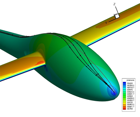
 Glider skin is colored according to local pressure, and friction lines are plotted, which are showing the flow direction right onto the skin. Those lines are illustrating how much locally the airflow is being "deformed" by fuselage presence, and in particular the way it is flowing laterally in symetry plane when sideslip is present. 

We can consider that the friction line at one location on the glider is giving the orientation of yaw string placed there - given a whool string is very thin compared to glider size & very close to fuselage skin. With appropriate post processing, the angle of friction lines versus glider symetry plane can be numerically evaluated from CFD output, and used for further analysis

CFD results in several condition  have been considered, to characterize yaw string response to glider parameters. Here is the plot of for yaw string angle computed for a typical canopy location, with Aoa ranging between 0 & 8 deg, and Sideslip between 0 & 8deg as well

Yaw string angle in relation to sideslip

The following observation can be made

  • Yaw string angle mostly respond to glider sideslip, and there is more yaw string angle than actual sisdeslip: yaw string is an amplifier for glider sideslip
  • In term of magnitude, typical "yaw string gain" is 2.5, that is when sideslip is 1deg, yaw string angle reads 2.5deg.
  • To a lesser extend, response of yaw string to sideslip evolves slightly with aoa - that is "yaw string gain" evolves slightly between cruise & circling phases

Another type of investigation can be made from CFD : when fixing the glider conditions, the gain of yaw string can be computed for various position over the glider. The following curve can be plotted, that gives the yawstring gain versus its relative positionning versus nose, in proportion to maximum height.
(e.g : Nose distance/max fuse height=0.85 on a 80cm high fuselage means yawstring is placed 0.85*90=76.5cm away from the nose)

Yaw string gain in relation to yaw string positionning vs fuselage nose

From this curve, it can be observed that the more forward on fuselage is (Nose distance/max fuse height toward 0), the greater the yaw string gain is, that is the more the yaw string amplifies the sideslip. This may help you tune the position of your yaw string, depending how much you want it to be active.

A small statistical study for yaw string positioning over 8 modern single seaters of various class, and 3 double seaters has been performed, with following findings :

  • On single seater or in forward seat of double seater, yaw string generaly lies between 0.85 & 1.05 times the max fuselage height from nose, meaning yaw string gain is in the range of 2.4 to 2.6
  • For the instructor seat of double seater, yawstring lies much further back, close to 2 times the max height from the nose : in that region yaw string gain is expected to be much closer to 1. That is instructor reads less sideslip from yaw string than his pupil does !

For sure there are exception to this rule when glider fuselage shape is out of the ordynary - typically yawstring gain on a Libelle would likely show a somewhat different behavior.

May be you will now look differently to your yaw string when you are flying !